Eneter U-Boot console on BeagleBone Black Wireless
by Mike Krinkin
I’m going through Bootlin training materials on embedded systems and LinuxKernel. In the training materials they use BeagleBoneBlack or [BeagleBonBlackWireless] boards.
This post covers how to connect the board and drop into U-Boot console, as well as hardware required. I’m using BeagleBoneBlackWireless, but the same should apply to BeagleBoneBlack giving that we don’t use any wireless capabilities of the board.
The hardware
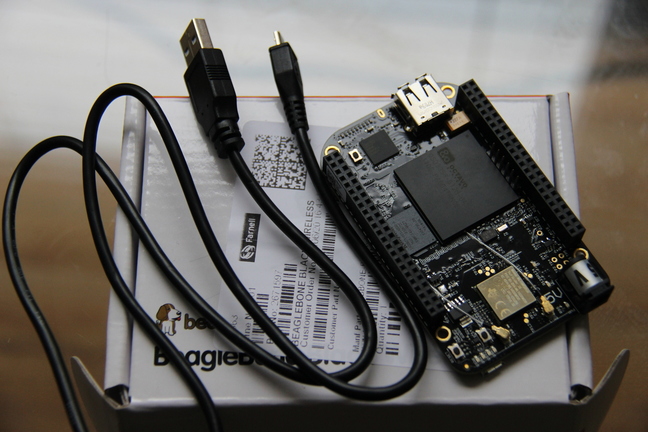
The actual board I have is BeagleBoneBlackWireless that I bought via Farnell, but I’d assume that any distributor will work as long as you get the board. Together with the board comes a micro USB to USB A cable that can also be used to power the device from your computer.
NOTE: There is no memory card or a separate power adapter included in the package, but fortunately enough I don’t need any of that so far.
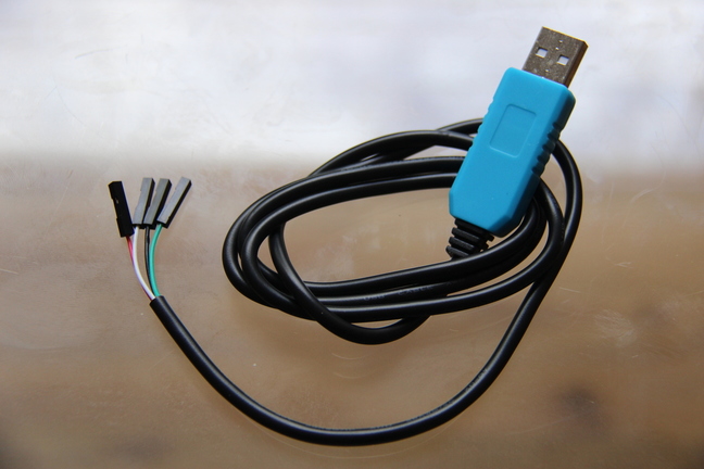
In addition to the board itself I need a USB to UART converter to connect to the debug serial port on the board. The BeagleBoneBlackSRM recommends to use an FTDI based USB to UART converter (see paragraph 7.5 Serial Header). I persoanlly used a cable based on Prolific chip instead.
NOTE: looking through various blocks and posts I found out that people mostly recommend using more expensive FTDI based adapters instead of Prolific based. However it also seems that the problems with the Prolific chips tend to happen on Windows. I’m using Linux, so it doesn’t appear to be a problem for me and I should worry more about the build quality than the chip itself.
That’s basically all the hardware that is needed, however one additional thing to mention. Both the cable included with the board itself as well as the USB to UART converter I use are USB A cables. So if you is like me and your computer doesn’t have USB A ports, then you should also make sure that you have an USB hub to be able to connect all those USB A cables to your computer.
The software
I use OEM version of Ubuntu 18.04.4 LTS from Dell, but for what I’m planning to do almost any Linux distribution will do. Just keep in mind that because I’m using Ubuntu the instalation commands will use apt.
Fortunately for the simple task of getting into U-Boot console we don’t need much. All we need is a tool to read and write from a charater device that will represent our USB-to-UART convertor.
Following the advice from Bootlin materials I used picocom:
sudo apt-get install picocom
Assembling
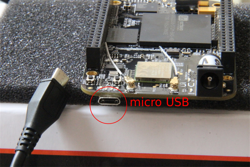
Now all we need to do is to assemble and connect everything. Let’s start with the simplest part - use the cable that came with the board to power it up.
With the UART it’s a tiny bit more complicated. Basically we need to connect three wires: RX, TX and GND. GND of the USB-to-UART adapter has to be connected to the GND pin of the serial header on on the board. USB-to-UART RX has to be connected to the board TX and USB-to-UART TX has to be connected to the board RX.
Now the question is what pins on the serial header on the board are RX, TX and GND? The BeagleBoneBlackSRM should ideally have this information, but I couldn’t find it there, so I found it in Bootlin training materials:
| Pin Number | Function |
|---|---|
| 1 | GND |
| 4 | RX |
| 5 | TX |
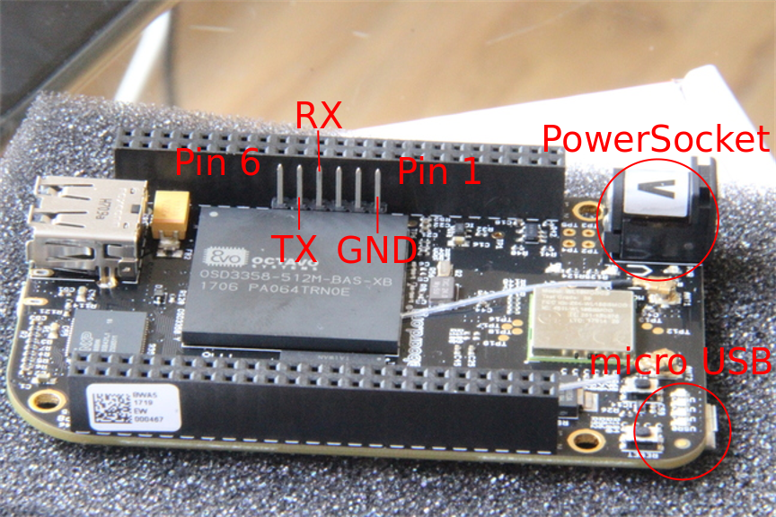
The serial header has 6 pins, but we only need 3 of them. I numbered pins starting from 1, where the ping number 1 is the one closest to the power supply socket and the micro USB connector we use for power. See the picture:
NOTE: We could figure out the pins by trying different combinations, but that’s a terrible if you’re just starting. Imaging, for example, that your USB-to-UART adapter doesn’t work or just flimsy. You may spend tons of time just to find out that your adapter doesn’t work. On the other hand, if you buy the cable that the BeagleBoneBlackSRM recommends, then you wouldn’t have this problem.
The final question is what pins of the USB-to-UART converter are GND, RX and TX. Naturally, that depends on what cable you use, but in the one I have:
- The black wire is GND
- The green wire is cable TX (needs to be connected to the board RX)
- The white wire is cable RX (needs to be connected to the board TX).
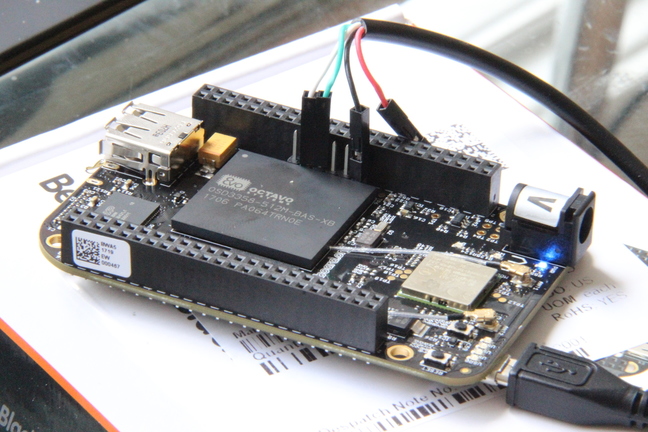
The complete setup with all wires connected looks like the picture above. If the device has power you should be able to see the blueish LED light close to the power socket.
U-Boot console
So now when the device is wired and powered up let’s use the debug serial port to access the U-Boot console. The device debug serial port operates using the 115200 baud rate, 8 data bits with no parity and one stop bit. This information is nowhere to be found in the BeagleBoneBlackSRM, but it seems to be a sort of unofficial standard configuration.
All it takes to connect to the device using picocom is the following command:
sudo picocom -b 115200 /dev/ttyUSB0
Here I assume that the USB-to-UART adapter is represented in the system as /dev/ttyUSB0, which should be the case unless you have some other serial devices connected via USB.
After connecting to the console reset the device using the RESET button right on top of the micro USB socket we use tu power up the device. You should see messages showing up in the picocom output:
U-Boot SPL 2017.05-rc1-00002-g35aecb22fe (Apr 05 2017 - 16:51:58)
Trying to boot from MMC2


U-Boot 2017.05-rc1-00002-g35aecb22fe (Apr 05 2017 - 16:51:58 -0500), Build: jenkins-github_Bootloader-Builder-541

CPU  : AM335X-GP rev 2.1
I2C:   ready
DRAM:  512 MiB
Reset Source: Global external warm reset has occurred.
Reset Source: Power-on reset has occurred.
MMC:   OMAP SD/MMC: 0, OMAP SD/MMC: 1
Using default environment

<ethaddr> not set. Validating first E-fuse MAC
BeagleBone Black:
Model: BeagleBoard.org BeagleBone Black Wireless:
BeagleBone: cape eeprom: i2c_probe: 0x54:
BeagleBone: cape eeprom: i2c_probe: 0x55:
BeagleBone: cape eeprom: i2c_probe: 0x56:
BeagleBone: cape eeprom: i2c_probe: 0x57:
Net:   eth0: MII MODE
Could not get PHY for cpsw: addr 0
cpsw
Press SPACE to abort autoboot in 2 seconds
Now we have access to the debug serial port on the BeagleBoneBlackWireless. As the message in the output suggest you should press SPACE before U-Boot starts loading Linux if you want to stay in the U-Boot console.
Instead of conclusion
Getting into U-Boot console is a simple technical tasks. All it takes is to follow the instructions. That being said you may discover a few unpleasent surprises along the way, like gaps in the documentation. Closing those gaps might time consuming, so hopefully the above description is detailed enough to make your life a bit simpler.
In one of the future posts I will try to cover building a new Linux Kernel for the BeagleBoneBlackWireless from the upstream sources, configuring U-Boot to load the kernel image and copiled device tree remotely from your workstation and, maybe, creating a simple driver based on the Bootlin materials.
tags: beaglebone - uboot