I continue going through Bootlin training materials on embedded systems and Linux Kernel. In the previous post I covered the basics of cross compiling modules for the BeagleBone Black or BeagleBone Black Wireless as well as an brief introduction into Device Tree.
In this article we will properly configure I2C bus on the board, connect our Nintendo Wiichuk device to the board and check that it’s recognized by the board.
Preparations
There is a set of awesome tools that we can use to check if our I2C configuraiton is working and what devices are connected to the I2C on the board: I2C tools.
We need to download the sources for the I2C tools and cross compile them for the BeagleBone Black or BeagleBone Black Wireless:
cd ~/ws
git clone git://git.kernel.org/pub/scm/utils/i2c-tools/i2c-tools.git
cd i2c-tools
export CC=arm-linux-gnueabi-gcc
export USE_STATIC_LIB=1
make
cp tools/i2cdetect ~/ws/nfsroot/bin
NOTE: ~/ws is the directory where I store all the sources and tools, you may have noticed that the Linux Kernel sources are also stored there.
NOTE: ~/ws/nfsroot is the root file system that I share with the board over NFS. Copying i2cdetect makes the binary available on the board.
NOTE: we explicitly specify the compiler to use via CC variable to cross compile the tools for the ARM architecture.
NOTE: USE_STATIC_LIB=1 statically compiles the binary, so that it does not depend on any shared library that the board may not have. It makes it slightly easier to cross compile the binary and copy it to the device.
Pin Multiplexing
Let’s now return to the Device Tree and I2C configuration. In the previous post we convered a minimal Device Tree configuration that made the bus and the device “discoverable”.
The proper configuration of the bus on the board would require a bit more than that. It appears to be a common practice that the same pin on a board may have multiple mutually exclusive functions.
NOTE: I suspect that there are economical reasons for that. I’d speculate that it’s more economical to devlop and produce a slightly more generic chip even though not all the consumers will use all the functions at the same time.
Whatever is the reason for that we need to configure the pins on the board properly. Basically, we need to tell the board that a particular cpin will be used as I2C data pin and another pin as I2C clock pin in this particular configuration.
Naturally, there is a programming interface to configure pins on the board, but at this point we don’t really need to know how exactly it works to be able to use. The reason is that there is already a pin multiplexing framework implemented all we need is to provide information how to configure the pins we need.
There are multiple ways to interact with the pin multiplexing framework, but one simple way to do that is to record the configuration in the Device Tree. Unfortunately, the configuration does not have a common standard or format. The format of the configuration is defined by the specific pin controller driver.
In our configuration we will use pinctrl-single. The source code for the driver lives in drivers/pinctrl/pinctrl-single.c, so you can take a look at how exactly it parses the configuration, so it’s not really easy to grasp it from the first look.
We will reuse the pin controller configuration already provided for the board, but we need to specify configuration of pins used by the second I2C controller since it’s not already provided. Here is how the Device Tree configuration looks now:
#include "am335x-boneblack-wireless.dts"

&am33xx_pinmux {
        i2c1_pins: pinmux_i2c1_pins {
                pinctrl-single,pins = <
                        AM33XX_PADCONF(AM335X_PIN_SPI0_D1, PIN_INPUT_PULLUP, MUX_MODE2)
                        AM33XX_PADCONF(AM335X_PIN_SPI0_CS0, PIN_INPUT_PULLUP, MUX_MODE2)
                >;
        };
};

&i2c1 {
        pinctrl-names = "default";
        pinctrl-0 = <&i2c1_pins>;

        status = "okay";
        clock-frequency = <100000>;

        nunchuk: nunchuk@52 {
                compatible = "nintendo,nunchuk";
                reg = <0x52>;
        };
};
Here I updated the am33xx_pinmux node that represents the pin controller of the board. In the node I added the configuration for pins used by the second I2C controller.
As you may remember I2C needs just a couple of pins: one for data and another for the clock signal. Each AM33XX_PADCONF macro describes a pin as a pair of numbers: offset of the register for the pin and the configuration of the pin.
NOTE: how do we know how to configure the pins and use the AM33XX_PADCONF macro? Well, ideally we should be able to figure it out from the board/processor documentation. However I cheated and copied the configuration from the arch/arm/boot/dts/am335x-evm.dts - Device Tree configuration for a board based on the same chip as my BeagleBone Black Wireless.
All that relains to do is to link the pin configuration to the second I2C controller by specifing the pinctrl-0 property in the second I2C controller node. You can learn about this binding from pinctrl-bindings.txt.
After updating the Device Tree configuration we need to rebuild it and copy to the TFTP directory so that U-Boot can pick it up:
cd ~/ws/linux
export CROSS_COMPILE=arm-linux-gnueabi-
export ARCH=arm
make dtbs
sudo cp arch/arm/boot/dts/am335x-boneblack-wireless-custom.dtb /var/lib/tftpboot/am335x-boneblack-wireless.dtb
If after you reboot the board it loads without breaking it’s a good sign. However we can go a little bit further use the i2cdetect tool we built earlier to quickly test the configuration:
i2cdetect -l
i2c-1	i2c       	OMAP I2C adapter                	I2C adapter
i2c-2	i2c       	OMAP I2C adapter                	I2C adapter
i2c-0	i2c       	OMAP I2C adapter                	I2C adapter
The command above lists the available I2C busses installed. We can also query I2C bus controller to check the available functionalities:
i2cdetect -F 1
Functionalities implemented by bus #1
I2C                              yes
SMBus quick command              no
SMBus send byte                  yes
SMBus receive byte               yes
SMBus write byte                 yes
SMBus read byte                  yes
SMBus write word                 yes
SMBus read word                  yes
SMBus process call               yes
SMBus block write                yes
SMBus block read                 no
SMBus block process call         no
SMBus PEC                        yes
I2C block write                  yes
I2C block read                   yes
Nintendo Wiichuk
Now let’s connect the Nintendo Wiichuk device to the board. We need four male-male wires to connect the deivce:
- two wires for power and ground to power up the device
- two wires for I2C itself.
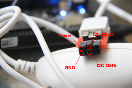
The Nintendo Wiichuk device comes with a ten pin connector. The picture above shows which pins we need and what they are responsible for.
NOTE: the connector is not simmetric, so pay attention to the notch on the connector to get the orientation right.
On the board we have even more pins. We need pins on what the documentation on the board refers to as P9 expansion header.
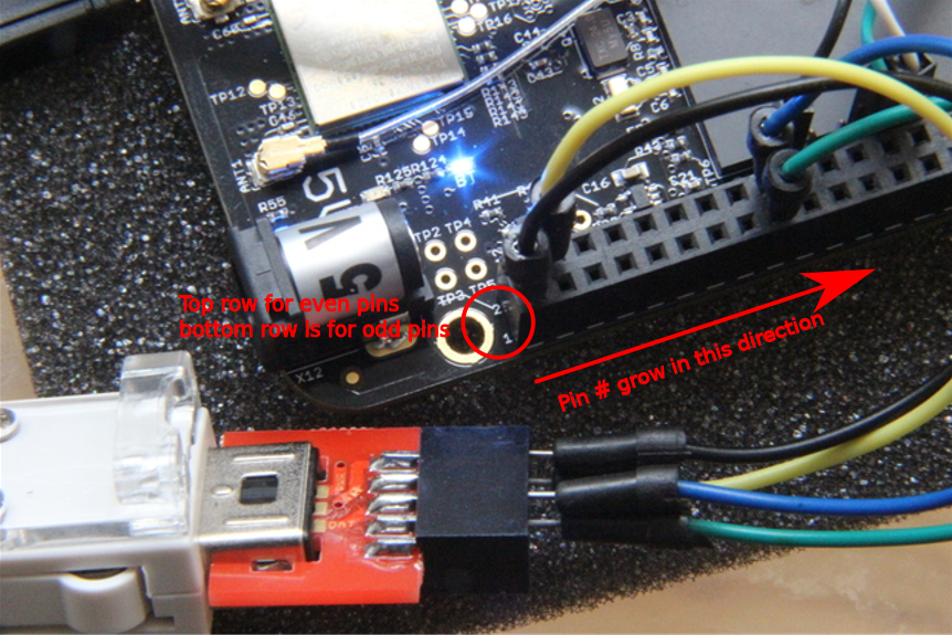
On the P9 expnasion header pins 1 and 2 are ground and we can use any of them. Pins 3 and 4 are 3.3 V power supply and we can use any of them for power. Pins 17 and 18 are usedused for I2C clock and data correspondingly.
NOTE: the picture above shows how the pins are numbered on the board so that you can find the right pin. For example, I used pin 1 for ground and pin 4 for power on the picture above.
Once the device is connected to the board we can use the i2cdetect again to probe a range of I2C addresses to see if somebody responds:
i2cdetect -r 1
i2cdetect: WARNING! This program can confuse your I2C bus
Continue? [y/N] y
     0  1  2  3  4  5  6  7  8  9  a  b  c  d  e  f
00:          -- -- -- -- -- -- -- -- -- -- -- -- --
10: -- -- -- -- -- -- -- -- -- -- -- -- -- -- -- --
20: -- -- -- -- -- -- -- -- -- -- -- -- -- -- -- --
30: -- -- -- -- -- -- -- -- -- -- -- -- -- -- -- --
40: -- -- -- -- -- -- -- -- -- -- -- -- -- -- -- --
50: -- -- 52 -- -- -- -- -- -- -- -- -- -- -- -- --
60: -- -- -- -- -- -- -- -- -- -- -- -- -- -- -- --
70: -- -- -- -- -- -- -- --
As you can see in my case the tool has found something on I2C address 0x52 which is the address Nintendo Wiichuk uses. So it’s an indicator that our device is connected correctly and can respond to the I2C commands.
NOTE: try to disconnect the device and run the command again.
Instead of the conclusion
We didn’t get to write any code this time, but now we know how to connect the device to the board and check the board I2C configuration and the device. Next time we will try to change the driver to actually communicate with the device.