FTDI protocol
by Mike Krinkin
In the previous post I touched a little bit on Vendor and Product IDs and changed the Vendor and Product IDs on the FTDI MPSSE cable that I got. I used the FTDI userspace library, but since the goal is to make a USB driver for the kernel in the end, we need to understand how the FTDI library calls are mapped to actual USB data transfers. This post covers what I did.
All the sources used in this article are available on GitHub.
The Problem
There are two parts to our usecase: MPSSE protocol and the FTDI configuration. MPSSE protocol is actually well described in the FTDI documentation: MPSSE.
I swear that I even managed to find in the documentation that MPSSE commands should be bufferred and sent to the bulk endpoint of the device, however I cannot find this documentation now. I will show later however how to confirm it though.
It would be reasonable to assume that reading data back also should be done by accessing the bulk endpoint of the device. Though, as it turned out there is a bit of a quirk with it.
However before we can use MPSSE, we should configure the FTDI chip to put it in the MPSSE mode. And that part is not covered by the documentation. Sources of the FTDI userspace driver are not readily available and the driver is distributed prebuilt.
So I need to do a little bit of reverse engineering to figure out how the FTDI library calls map to the USB data transfers. Of course we don’t need to reverse engineer all the library calls, but only those that we actually need.
I2C example
We will start with an I2C example using the userspace FTDI library. I will not cover the code of the example, because there is an FTDI document that covers all the important parts: USB-to-I2C.
Using the documentation we can realtively easily come up with the code that does some I2C data transfers. However, we also need some hardware to make sure that the code works.
I will use the Nintendo Wiichuk controller that I used before, since it’s the only I2C device I have. To connect the controller to the MPSSE cable I have I also used a breadboard, though it may have been an overkill.
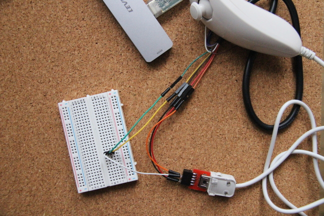
Out of ten pins of the MPSSE cable we need five: GND (black), PWR (red), SCL (orange) and SDA-in and SDA-out (green and yellow, and it doesn’t matter which one is which). Normally for SDA we need just one cable/pin, but since MPSSE cable wasn’t specifically designed to support I2C we need a bit of hacking. We need to combine two MPSSE pins together to act as one SDA pin (that’s what I used the breadboard for).
After connecting the device and running the code that comminucates with the I2C device we can check that the code works. With the setup ready we can actually start reverse engineering the protocol.
USB snooping
The userspace FTDI library somehow needs to communicate with the kernel or at
least that was my first instinct. So the first tool I used is strace with the
-f flag to see what system calls the library uses.
Strace produces a lot of output, so in general it might not be easy to understand what parts are relevant. Here is a small snippet of the produced output:
[pid  6437] mprotect(0x7fde14000000, 135168, PROT_READ|PROT_WRITE) = 0
[pid  6437] read(6, "\1", 1)            = 1
[pid  6437] poll([{fd=6, events=POLLIN}], 1, 100) = 0 (Timeout)
[pid  6437] poll([{fd=6, events=POLLIN}], 1, 100 <unfinished ...>
[pid  6435] <... openat resumed> )      = 8
[pid  6435] ioctl(8, USBDEVFS_GET_CAPABILITIES, 0x5637b30631f0) = 0
[pid  6435] write(7, "\1", 1)           = 1
[pid  6437] <... poll resumed> )        = 1 ([{fd=6, revents=POLLIN}])
[pid  6435] ioctl(8, USBDEVFS_SUBMITURB <unfinished ...>
[pid  6437] read(6,  <unfinished ...>
[pid  6435] <... ioctl resumed> , 0x5637b3063580) = 0
[pid  6437] <... read resumed> "\1", 1) = 1
[pid  6435] futex(0x5637b3061480, FUTEX_WAIT_PRIVATE, 2, NULL <unfinished ...>
[pid  6437] futex(0x5637b3061480, FUTEX_WAKE_PRIVATE, 1 <unfinished ...>
[pid  6435] <... futex resumed> )       = -1 EAGAIN (Resource temporarily unavailable)
[pid  6437] <... futex resumed> )       = 0
[pid  6435] futex(0x5637b3061480, FUTEX_WAKE_PRIVATE, 1 <unfinished ...>
[pid  6437] poll([{fd=6, events=POLLIN}, {fd=8, events=POLLOUT}], 2, 100 <unfinished ...>
[pid  6435] <... futex resumed> )       = 0
[pid  6437] <... poll resumed> )        = 1 ([{fd=8, revents=POLLOUT}])
[pid  6435] futex(0x5637b3061478, FUTEX_WAIT_BITSET_PRIVATE|FUTEX_CLOCK_REALTIME, 0, {tv_sec=1598105111, tv_nsec=658779344}, 0xffffffff <unfinished ...>
[pid  6437] ioctl(8, USBDEVFS_REAPURBNDELAY, 0x7fde19ad3d68) = 0
[pid  6437] ioctl(8, USBDEVFS_REAPURBNDELAY, 0x7fde19ad3d68) = -1 EAGAIN (Resource temporarily unavailable)
[pid  6437] futex(0x5637b3061478, FUTEX_WAKE_PRIVATE, 2147483647 <unfinished ...>
[pid  6435] <... futex resumed> )       = 0
[pid  6437] <... futex resumed> )       = 1
[pid  6435] futex(0x5637b3061428, FUTEX_WAIT_PRIVATE, 2, NULL <unfinished ...>
[pid  6437] futex(0x5637b3061428, FUTEX_WAKE_PRIVATE, 1 <unfinished ...>
In this case however a few ioctl calls with USBDEVFS_ commands caught my
attention. So I digged into the kernel code and found that those ioctl calls
are processed by usbdev_do_ioctl.
Looking through the function and what commands it supports, I got pretty
confident that those ioctl calls is how the userspace FTDI driver communicates
with the kernel.
With this information we can go and add some logging to the kernel to extract all the information we need to figure out the FTDI protocol. There are multiple ways to collect some logs/traces, but the most straighforward one would be to just modify the kernel code.
While trying to do exactly that however, I found that somebody already thought
of this before me. All the data transfers using those ioctl calls can be
logged using snoop_urb.
However by default logging was disabled on my system. This behavior is
controlled by the usbfs_snoop parameter. We can change the value of the
usbfs_snoop in runtime:
echo 1 > /sys/module/usbcore/parameters/usbfs_snoop
With this snooping enabled we can now run our testing code again and use dmesg
to check the kernel logs. Here is a small snippet of kernel logs with snooping
enabled:
[715828.150826] usb 1-1.4: opened by process 4533: i2c_read
[715828.150928] usb 1-1.4: usbdev_do_ioctl: SUBMITURB
[715828.150937] usb 1-1.4: control urb: bRequestType=80 bRequest=06 wValue=0300 wIndex=0000 wLength=00ff
[715828.150948] usb 1-1.4: userurb 00005639b6241570, ep0 ctrl-in, length 255
[715828.150976] usb 1-1.4: urb complete
[715828.150981] usb 1-1.4: userurb         pK-error, ep0 ctrl-in, actual_length 4 status 0
[715828.150985] data: 04 03 09 04                                                                                      ....
[715828.151083] usb 1-1.4: usbdev_do_ioctl: REAPURBNDELAY
[715828.151090] usb 1-1.4: reap 00005639b6241570
[715828.151107] usb 1-1.4: usbdev_do_ioctl: REAPURBNDELAY
[715828.151155] usb 1-1.4: usbdev_do_ioctl: SUBMITURB
[715828.151163] usb 1-1.4: control urb: bRequestType=80 bRequest=06 wValue=0303 wIndex=0409 wLength=00ff
[715828.151173] usb 1-1.4: userurb 00005639b62416b0, ep0 ctrl-in, length 255
[715828.152219] usb 1-1.4: urb complete
[715828.152226] usb 1-1.4: userurb         pK-error, ep0 ctrl-in, actual_length 18 status 0
[715828.152230] data: 12 03 46 00 54 00 33 00 45 00 4c 00 50 00 58 00 53 00                                            ..F.T.3.E.L.P.X.S.
[715828.152335] usb 1-1.4: usbdev_do_ioctl: REAPURBNDELAY
[715828.152343] usb 1-1.4: reap 00005639b62416b0
[715828.152359] usb 1-1.4: usbdev_do_ioctl: REAPURBNDELAY
[715828.152465] usb 1-1.4: usbdev_do_ioctl: CLAIMINTERFACE
[715828.152548] usb 1-1.4: usbdev_do_ioctl: SUBMITURB
[715828.152556] usb 1-1.4: control urb: bRequestType=80 bRequest=06 wValue=0300 wIndex=0000 wLength=00ff
[715828.152567] usb 1-1.4: userurb 00005639b62417f0, ep0 ctrl-in, length 255
[715828.152601] usb 1-1.4: urb complete
[715828.152605] usb 1-1.4: userurb         pK-error, ep0 ctrl-in, actual_length 4 status 0
[715828.152610] data: 04 03 09 04                                                                                      ....
[715828.152672] usb 1-1.4: usbdev_do_ioctl: REAPURBNDELAY
[715828.152695] usb 1-1.4: reap 00005639b62417f0
[715828.152707] usb 1-1.4: usbdev_do_ioctl: REAPURBNDELAY
[715828.152808] usb 1-1.4: usbdev_do_ioctl: SUBMITURB
[715828.152817] usb 1-1.4: control urb: bRequestType=80 bRequest=06 wValue=0303 wIndex=0409 wLength=00ff
[715828.152828] usb 1-1.4: userurb 00005639b6241930, ep0 ctrl-in, length 255
[715828.153989] usb 1-1.4: urb complete
Protocol
With all this information we now have a complete picture of what USB data transfers FTDI device uses. However figuring out what transfer associated with what FTDI library call still requires a bit of guessing and as such it’s hard to explain.
In my case I did modifications to the testing tool adding required FTDI library calls one by one and looking at what changed in the snooped logs. So I came with the following protocol.
All FTDI configuration commands were implemented as USB control transfers to the
endpoint zero of the device. Each control transfer contains a few parameters:
bRequest, bRequestType, wValue and wIndex. Those parameters are not
specific to the FTDI, all the USB control transfers have them.
In order to reset the FTDI device (FT_ResetDevice function) we need three
control data transfers:
bRequestis0x00,bRequestTypeis0x40,wValueis0x0000andwIndexis0x0000bRequestis0x00,bRequestTypeis0x40,wValueis0x0001andwIndexis0x0000bRequestis0x00,bRequestTypeis0x40,wValueis0x0002andwIndexis0x0000
NOTE: since I reverse engineered the protocol, I have no real understanding of the meaning of the individual command and whether all of them are actually necessary.
The next step of the FTDI device initialization is disabling special characters
(FT_SetChars function). That requires two USB control transfers:
bRequestis0x06,bRequestTypeis0x40,wValueis0x0000andwIndexis0x0000bRequestis0x07,bRequestTypeis0x40,wValueis0x0000andwIndexis0x0000
Then we need to call FT_SetBitMode twice, first to do another kind of reset
and then to change the mode of the FTDI device to MPSSE:
bRequestis0x0b,bRequestTypeis0x40,wValueshould be set to the mode (0x0000for reset and0x0200for MPSSE mode),wIndexis0x0000.
Those commands pretty much cover the initialization of the device and then configuring it to work in the MPSSE mode. In the MPSSE modes everything gets much easier as the protocol is documented and it boils down to writing to the the bulk endpoint.
However there is a quirk when we want to read the data back. To read the data from the FTDI we need to send a bulk data transfer request to the right endpoint, which is expected. I noticed however that the first two bytes returned from the bulk endpoint for each request are not part of the requested data. It’s my understanding that they represent some kind of status. I don’t really know how to interpret the status, so I always drop the first two bytes of the response I get from the FTDI.
Instead of conclusion
FTDI documentation intentionally does not cover the FTDI protocol, so before we can create a driver we need to understand it first. Fortunately enough, it’s not really hard to figure out the basics of the protocol and it doesn’t seem like FTDI Team has put in a lot of efforts to prevent users from doing it.
tags: usb - linux-kernel - ftdi